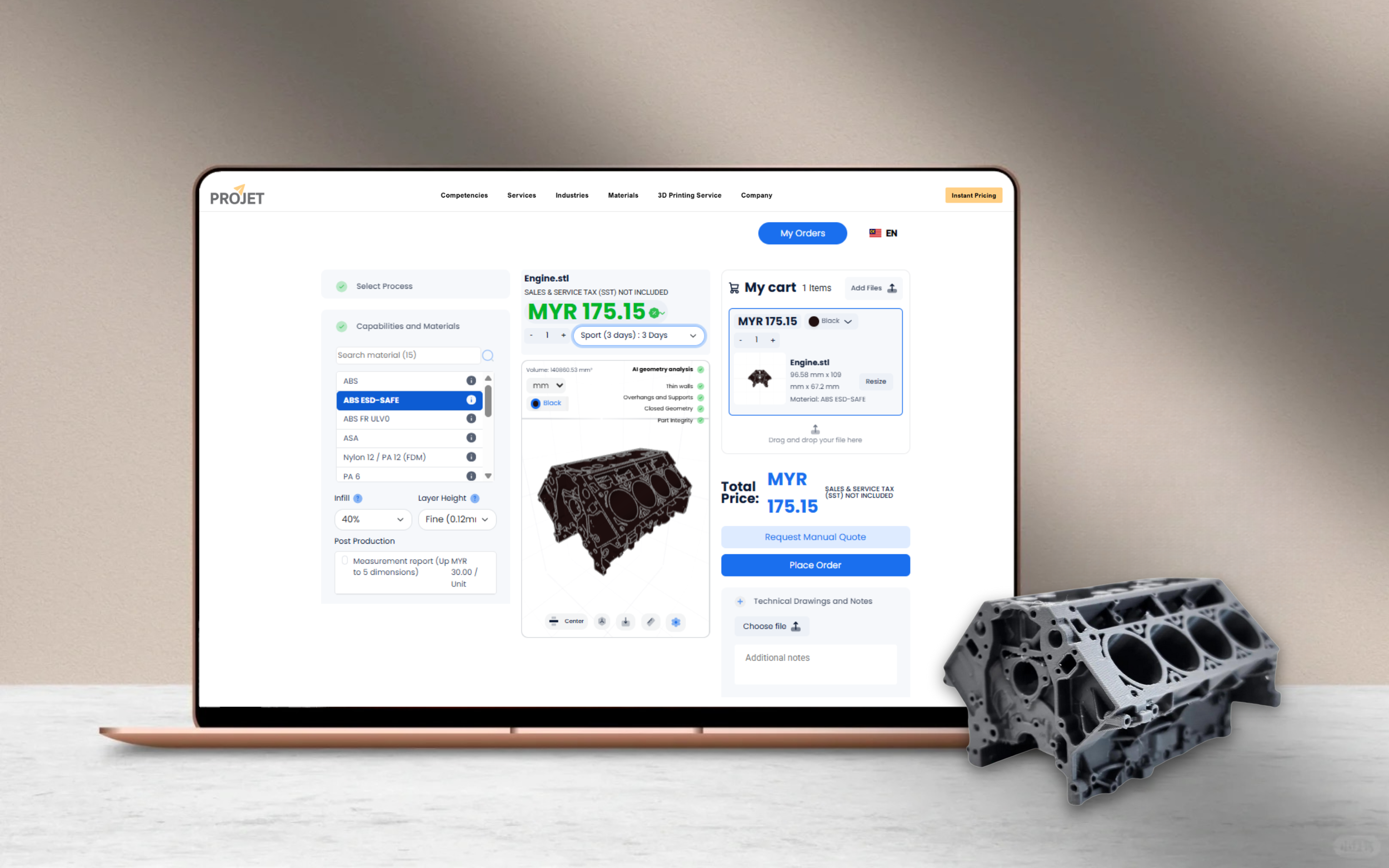
From CAD to 3D Printing: How to Create Custom Parts Fast
Evaluating build direction, support structures, radii placement, and wall thickness to optimize printed parts.
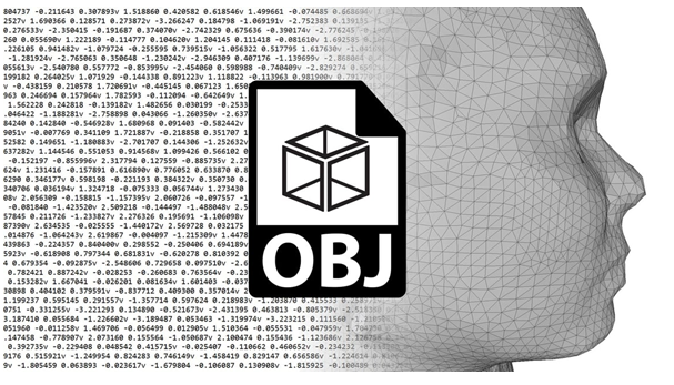
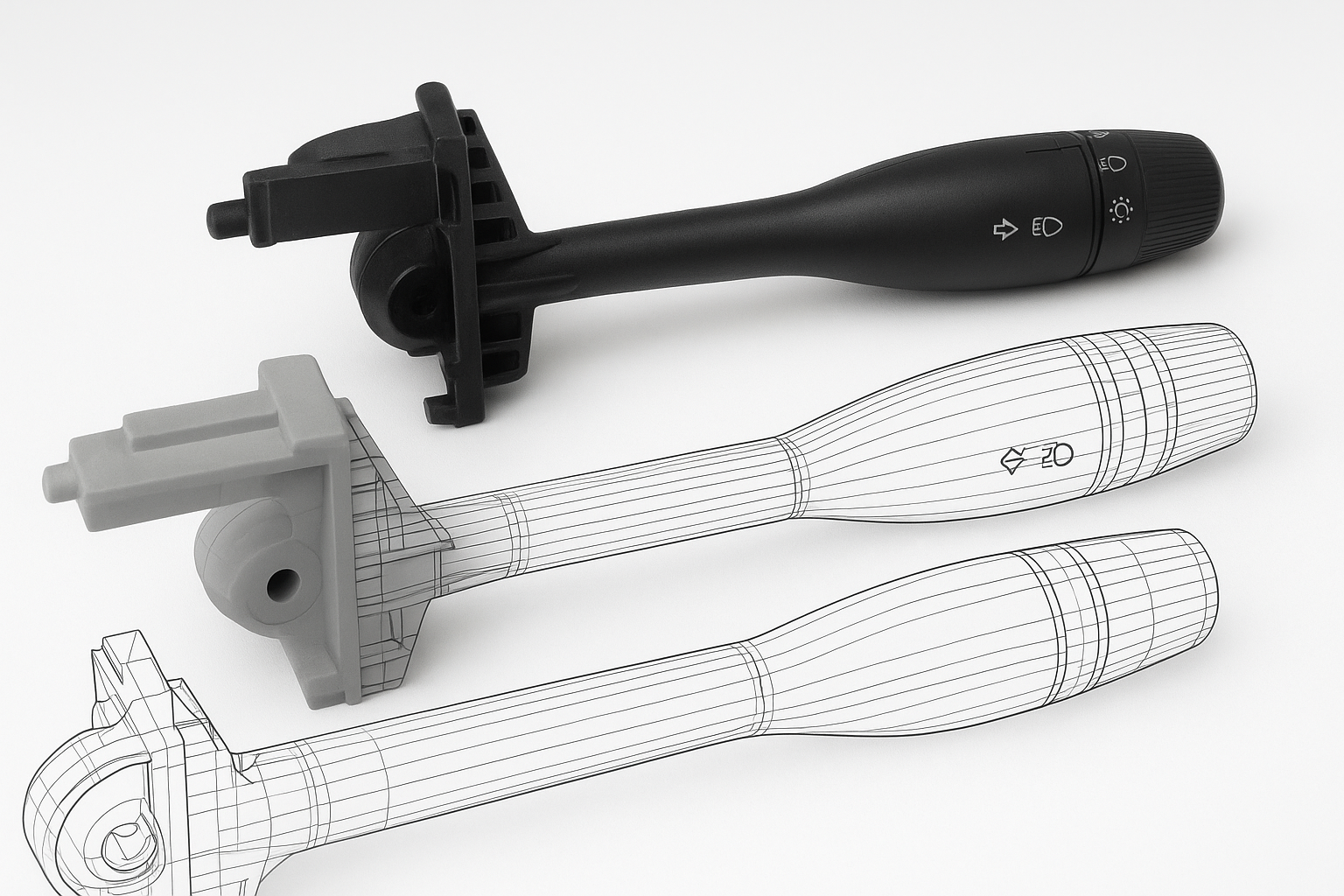
Designing for 3D printing is a little different than designing for traditional manufacturing. Since 3D-printed parts are built layer by layer, engineers face unique challenges when preparing CAD files. Even gravity influences the outcome! By following a few essential design considerations, you can significantly improve the accuracy, strength, and efficiency of your printed parts—no matter what CAD software you use.
The Effect of Build Direction on 3D Printing
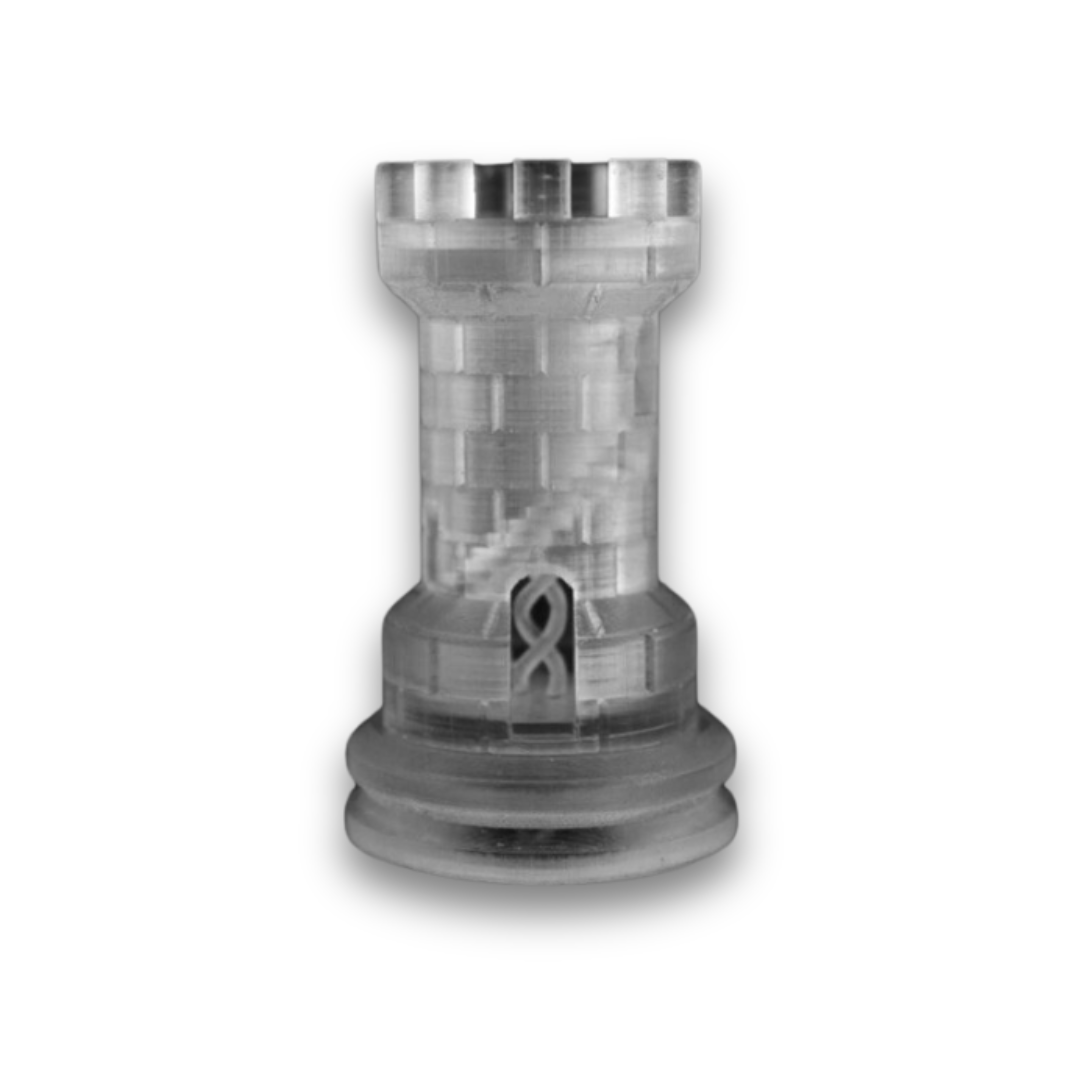
When creating or optimizing a part, your first major choice is the build direction. While shorter part heights usually mean quicker builds and lower costs, accuracy and strength often outweigh speed.
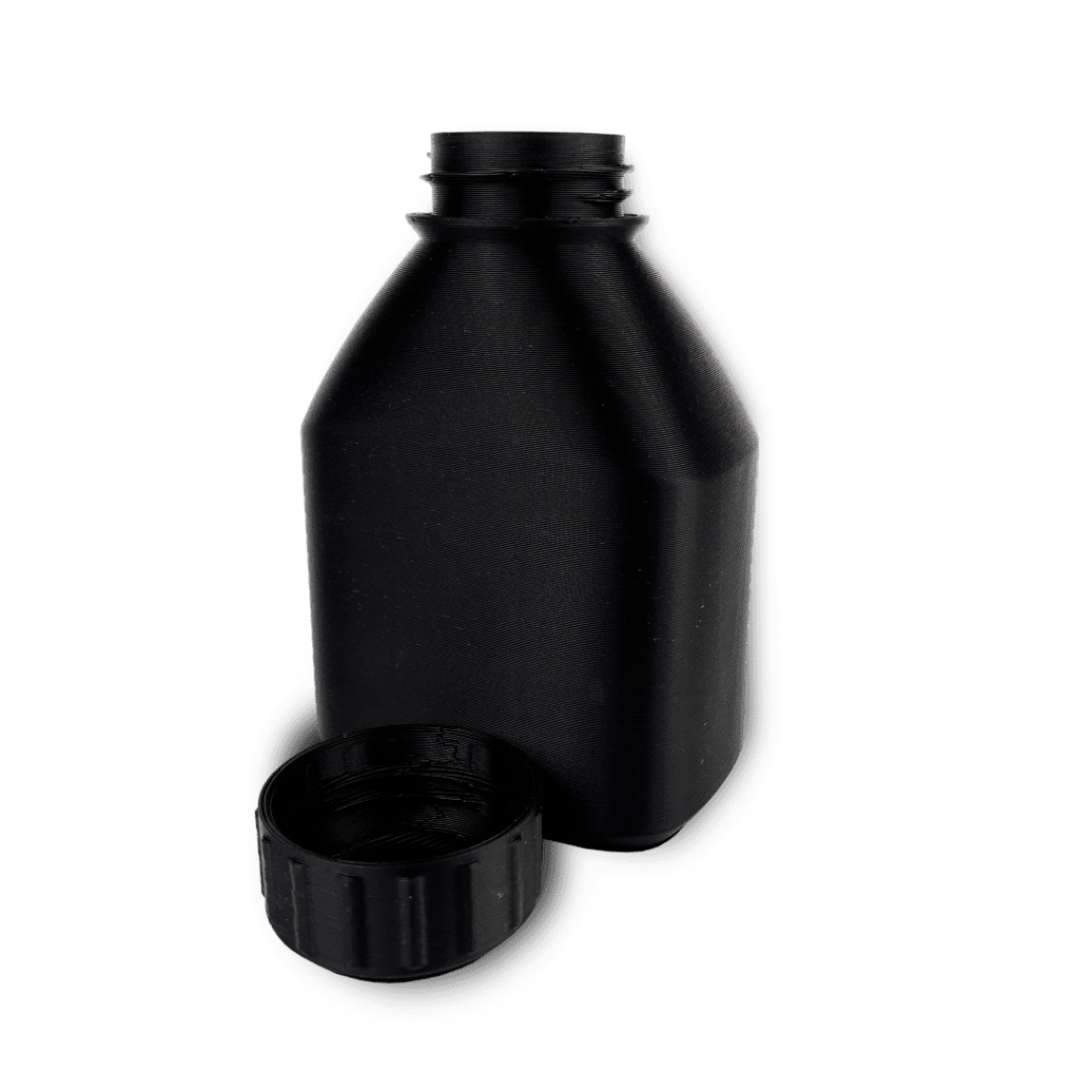
As a rule of thumb, orient the more detailed side of the part upward. Cylindrical features are also most accurate when their cross-section lies in the draw plane. Good orientation helps minimize both the need for support material and the impact of shrinkage caused by drastic cross-section changes.
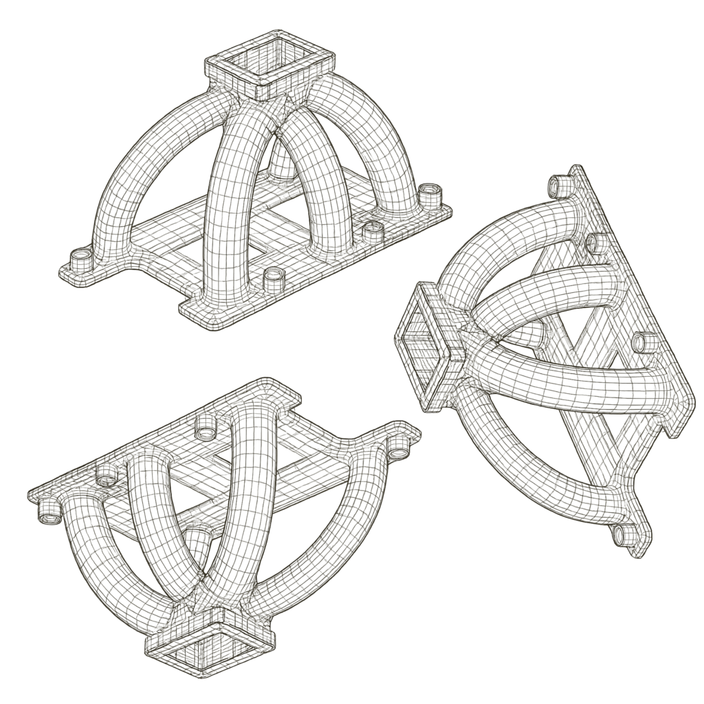
Example: If a cylinder faces upward, it prints more precisely than one positioned sideways. Rotating the model 45 degrees and giving it a flat base allows both cylinders to print consistently—and without heavy support requirements.
The 45-Degree Rule
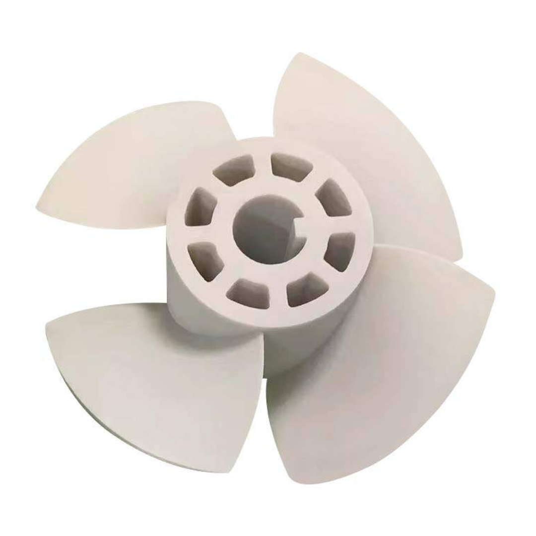
For most additive technologies requiring supports, surfaces at 45° or steeper can support themselves. Reducing supports is a key cost-saving strategy because every support adds material, time, and post-processing labor.
That said, some technologies differ: certain processes may need 55° or steeper angles, while powder-bed methods like SLS and MJF don’t require supports at all.
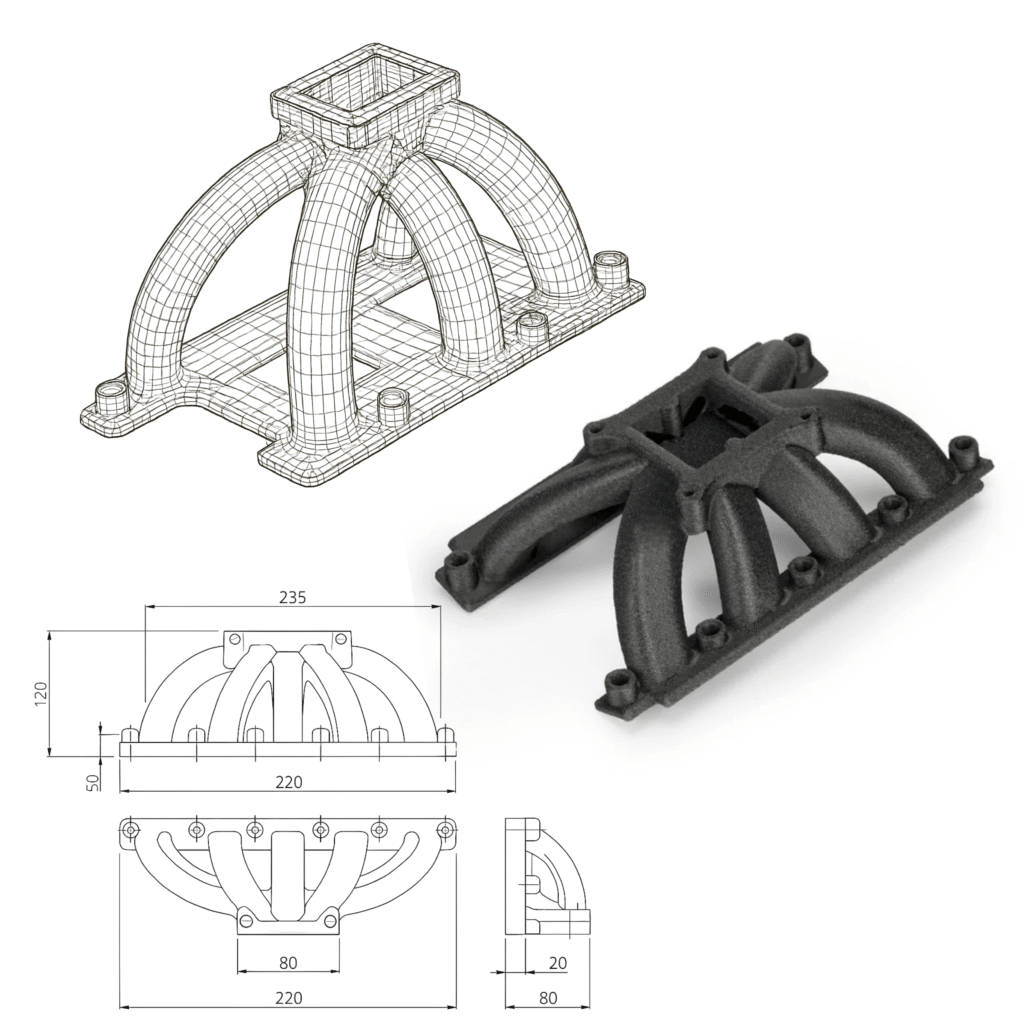
Add Radii to Strengthen Parts
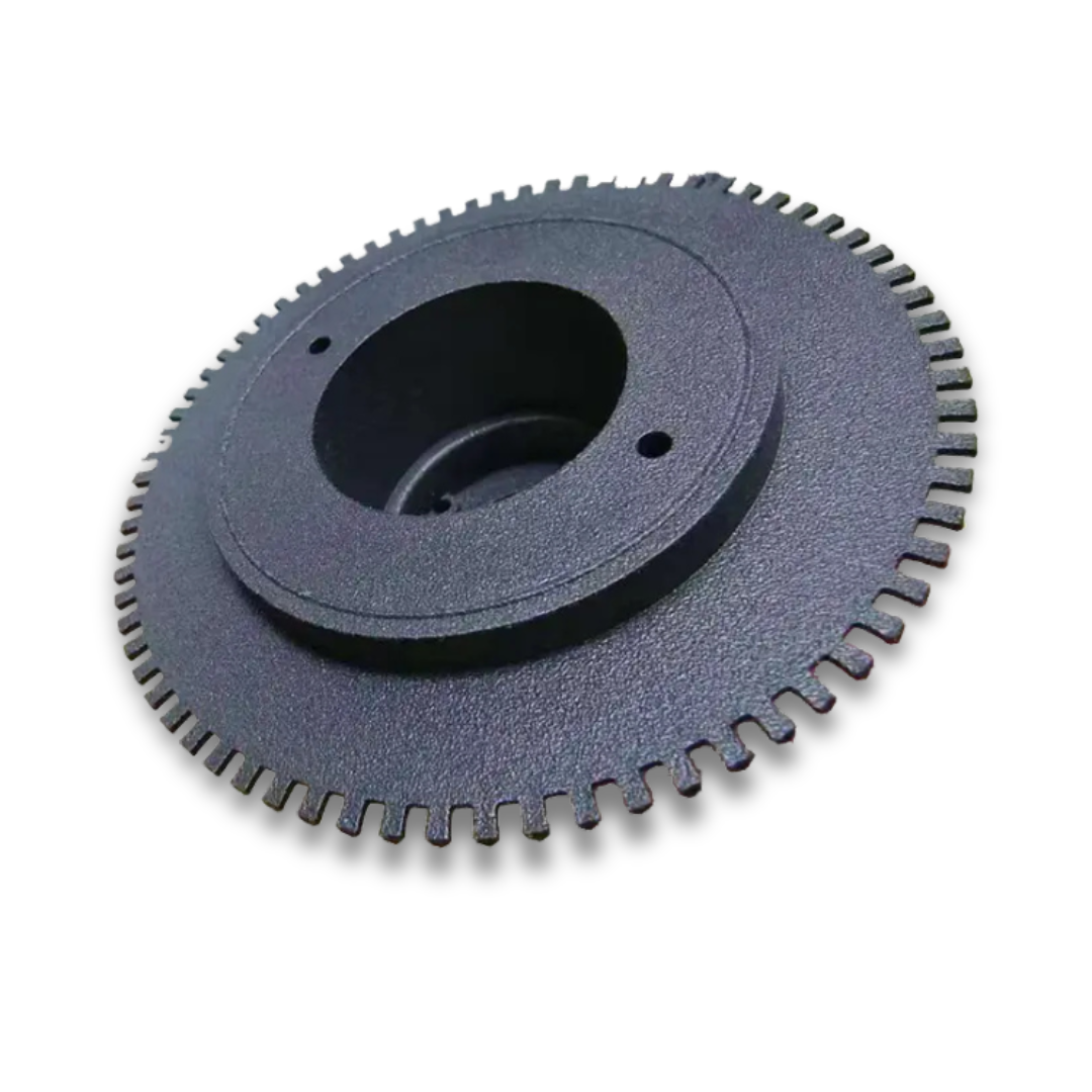
Adding radii (rounded edges) to sharp corners is one of the simplest ways to boost part performance. Radii reduce stress concentrations, improve accuracy by minimizing shrink-related defects, and help parts resist cracking under load.
In some cases—such as titanium parts produced with DMLS—radii aren’t optional. Without them, shrinkage can cause cracks during the print itself. Even a small radius (about 1 mm) can prevent this.
Pro tip: Fillets can also eliminate unsupported surfaces, and coring out large sections ensures more consistent wall thickness, which further improves quality.
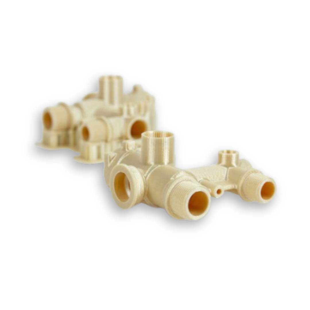
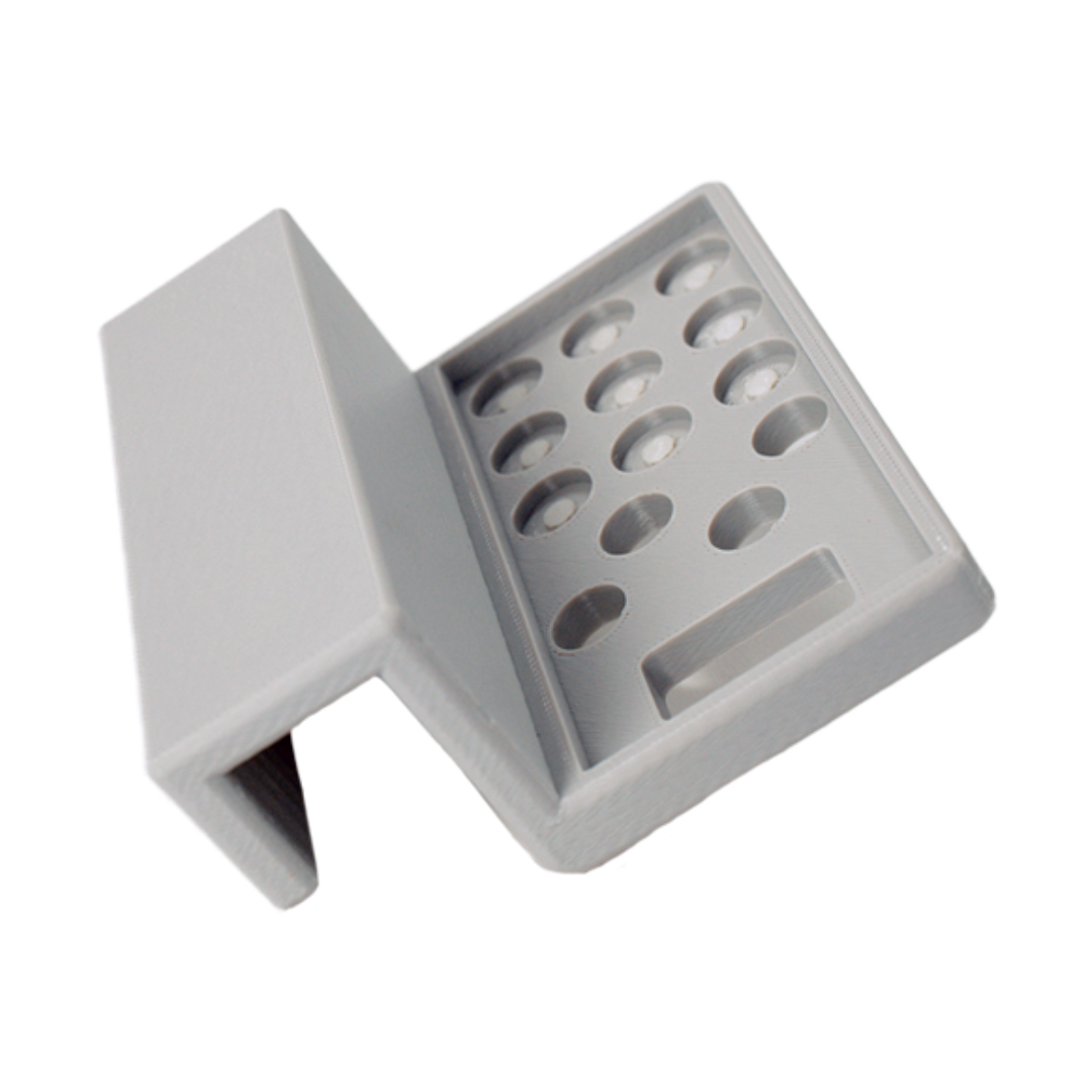
Maintain Uniform Wall Thickness
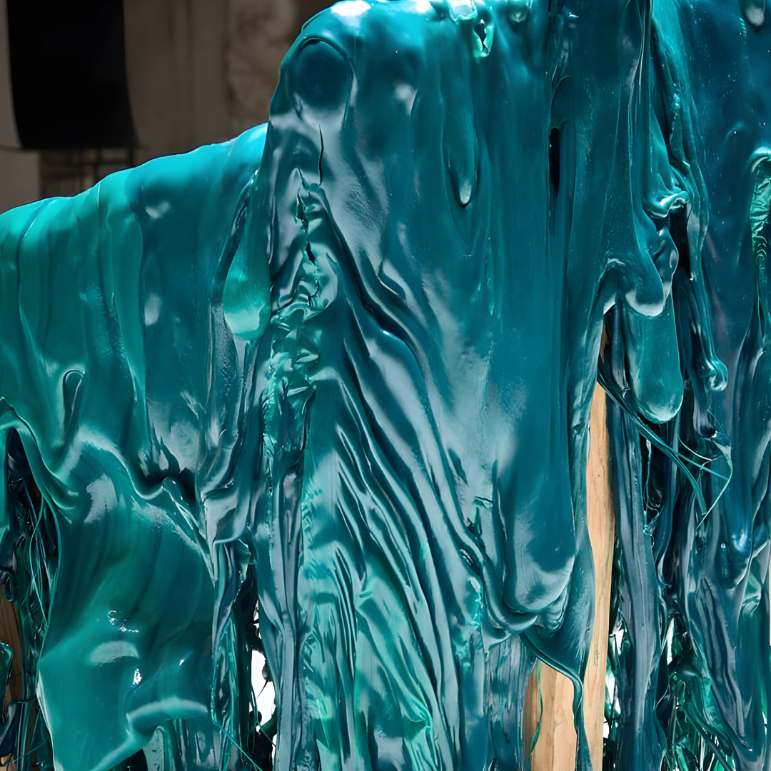
Large thickness variations often lead to shrinkage issues, affecting both aesthetics and dimensional accuracy. To prevent this, core out thicker areas where possible and leave cavities accessible for easy removal of supports or excess powder.
If you’re printing with FDM, you have more flexibility. Because of partial infill, FDM naturally maintains a fairly uniform structure—even when the CAD model doesn’t.
How Projet Helps
At Projet, we know that designing for additive manufacturing isn’t always straightforward. That’s why we go beyond printing parts—we help you get them right the first time. Our team and technology are here to:
Optimize your CAD files for build direction, geometry, and support reduction, ensuring smoother, stronger prints.
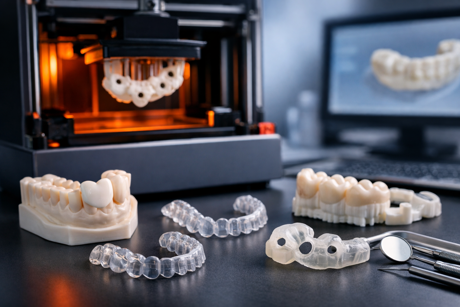
Advise on materials and processes—from SLS and MJF to DMLS and FDM—so you always choose the best fit for your project.
Enhance part reliability by validating radii, wall thickness, and transitions to minimize defects and improve durability.
Accelerate production timelines with streamlined quoting, fast turnaround, and scalable manufacturing options.
Support you at every stage—from prototyping to low-volume production—so you can innovate with confidence.
With Projet, you don’t just get 3D printing—you get a partner who helps transform your designs into high-quality, functional parts, delivered faster.
3D Printing Services
Instant Price